
This chapter describes how to use the Network Dispatcher Feature and contains the following sections:
Network Dispatcher uses load-balancing technology from IBM to determine the most appropriate server to receive each new connection. This is the same technology used in IBM's SecureWay (R) Network Dispatcher product for Solaris, Windows NT(R) and AIX(R).
Network Dispatcher is a feature that boosts the performance of servers by forwarding TCP/IP session requests to different servers within a group of servers, thus load balancing the requests among all servers. The forwarding is transparent to the users and to applications. Network Dispatcher is useful for server applications such as e-mail, World Wide Web servers, distributed parallel database queries, and other TCP/IP applications.
Network Dispatcher can also be used for load balancing stateless UDP application traffic to a group of servers.
Network Dispatcher can help maximize the potential of your site by providing a powerful, flexible, and scalable solution to peak-demand problems. During peak demand periods, Network Dispatcher can automatically find the optimal server to handle incoming requests.
The Network Dispatcher function does not use a domain name server for load balancing. It balances traffic among your servers through a unique combination of load balancing and management software. Network Dispatcher can also detect a failed server and forward traffic to other available servers.
All client requests sent to the Network Dispatcher machine are forwarded to the server that is selected by the Network Dispatcher as the optimal server according to certain dynamically set weights. These weights are calculated by Network Dispatcher based on a number of factors including connection counts, server load and server availability.
The server sends a response back to the client without any involvement of Network Dispatcher. No additional software is required on your servers to communicate with Network Dispatcher.
The Network Dispatcher function is the key to stable, efficient management of a large, scalable network of servers. With Network Dispatcher, you can link many individual servers into what appears to be a single, virtual server. Your site thus appears as a single IP address to the world. Network Dispatcher functions independently of a domain name server; all requests are sent to the IP address of the Network Dispatcher machine.
Network Dispatcher allows a management application that is SNMP-based to monitor Network Dispatcher status by receiving basic statistics and potential alert situations. Refer to "SNMP Management" in the Protocol Configuration and Monitoring Reference Volume 1 for more information.
Network Dispatcher brings distinct advantages in load balancing traffic to clustered servers, resulting in stable and efficient management of your site.
There are many different approaches to load balancing. Some of these approaches allow users to choose a different server at random if the first server is slow or not responding. Another approach is round-robin, in which the domain name server selects a server to handle requests. This approach is better, but does not take into consideration the current load on the target server or even whether the target server is available.
Network Dispatcher can load balance requests to different servers based on the type of request, an analysis of the load on servers, or a configurable set of weights that you assign. To manage each different type of balancing, the Network Dispatcher has the following components:
Network Dispatcher supports advisors for FTP, HTTP, SMTP, NNTP, POP3, and Telnet as well as a TN3270 advisor that works with TN3270 servers in IBM 2210s, IBM 2212s, and IBM 2216s, and an MVS(TM) advisor that works with Workload Manager (WLM) on MVS systems . WLM manages the amount of workload on an individual MVS ID. Network Dispatcher can use WLM to help load balance requests to MVS servers running OS/390(R) V1R3 or later release.
There are no protocol advisors specifically for UDP protocols. If you have MVS servers, you can use the MVS system advisor to provide server load information. Also, if the port is handling TCP and UDP traffic, the appropriate TCP protocol advisor can be used to provide advisor input for the port. Network Dispatcher will use this input in load balancing both TCP and UDP traffic on that port.
The manager is an optional component. However, if you do not use the manager, the Network Dispatcher will balance the load using a round-robin scheduling method based on the server weights you have configured for each server.
When using Network Dispatcher to load balance stateless UDP traffic, you must only use servers that respond to the client using the destination IP address from the request. See Configuring a Server for Network Dispatcher for a more complete explanation.
The base Network Dispatcher function has the following characteristics that makes it a single point of failure from many different perspectives:
All these characteristics make the following failures critical for the whole cluster:
In all these failure cases, which are not only Network Dispatcher failures but also Network Dispatcher neighborhood failures, all the existing connections are lost. Even with a backup Network Dispatcher running standard IP recovery mechanisms, recovery is, at best, slow and applies only to new connections. In the worst case, there is no recovery of the connections.
To improve Network Dispatcher availability, the Network Dispatcher High Availability function uses the following mechanisms:
Besides the basic criteria of failure detection, (the loss of connectivity between active and standby Network Dispatchers, detected through the Heartbeat messages) there is another failure detection mechanism named "reachability criteria." When you configure the Network Dispatcher, you provide a list of hosts that each of the Network Dispatchers should be able to reach to work correctly. The hosts could be routers, IP servers or other types of hosts. Host reachability is obtained by pinging the host.
Switchover takes place either if the Heartbeat messages cannot go through, or if the reachability criteria are no longer met by the active Network Dispatcher and the standby Network Dispatcher is reachable. To make the decision based on all available information, the active Network Dispatcher regularly sends the standby Network Dispatcher its reachability capabilities. The standby Network Dispatcher then compares the capabilities with its own and decides whether to switch.
The primary and backup Network Dispatchers keep their databases synchronized through the "Heartbeat" mechanism. The Network Dispatcher database includes connection tables, reachability tables and other information. The Network Dispatcher High Availability function uses a database synchronization protocol that insures that both Network Dispatchers contain the same connection table entries. This synchronization takes into account a known error margin for transmission delays. The protocol performs an initial synchronization of databases and then maintains database synchronization through periodic updates.
In the case of a Network Dispatcher machine or interface failure, the IP takeover mechanism will promptly direct all traffic toward the standby Network Dispatcher. The Database Synchronization mechanism insures that the standby has the same entries as the active Network Dispatcher, so existing client-server connections are maintained.
| Note: | Cluster IP Addresses are assumed to be on the same logical subnet as the previous hop router (IP router) as the previous hop router (IP router) unless you are using cluster address advertising. |
The IP Router will resolve the cluster address through the ARP protocol. To perform the IP takeover, the Network Dispatcher (standby becoming active) will issue an ARP request to itself, that is broadcasted to all directly attached networks belonging to the logical subnet of the cluster. The previous hops' IP router will update their ARP tables (according to RFC826) to send all traffic for that cluster to the new active (previously standby) Network Dispatcher.
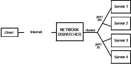
There are many ways that you can configure Network Dispatcher to support your site. If you have only one host name for your site to which all of your customers will connect, you can define a single cluster and any ports to which you want to receive connections. This configuration is shown in Figure 5.
Figure 5. Example of Network Dispatcher Configured With a Single Cluster and 2 Ports
 |
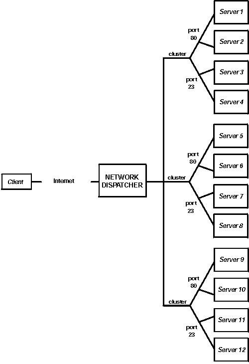
Another way of configuring Network Dispatcher would be necessary if your site does content hosting for several companies or departments, each one coming into your site with a different URL. In this case, you might want to define a cluster for each company or department and any ports to which you want to receive connections at that URL as shown in Figure 6.
Figure 6. Example of Network Dispatcher Configured With 3 Clusters and 3 URLs
 |
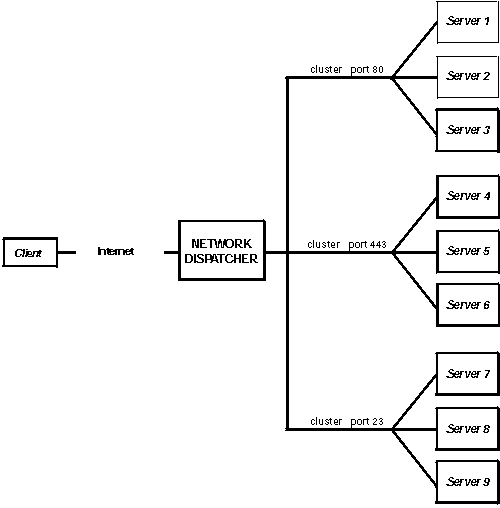
A third way of configuring Network Dispatcher would be appropriate if you have a very large site with many servers dedicated to each protocol supported. For example, you may choose to have separate FTP servers with direct T3 lines for large downloadable files. In this case, you might want to define a cluster for each protocol with a single port but many servers as shown in Figure 7.
Figure 7. Example of Network Dispatcher Configured with 3 Clusters and 3 Ports
 |
Before configuring Network Dispatcher:
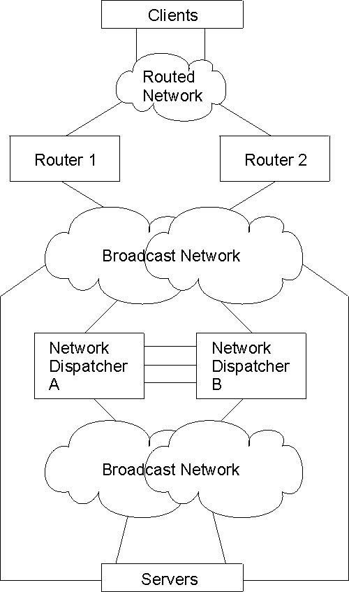
If high availability is important for your network, a typical high availability configuration is shown in Figure 8.
Figure 8. High Availability Network Dispatcher Configuration
 |
To configure Network Dispatcher on an IBM 2210:
| Note: | Cluster IP Addresses must not match the internal IP address of the router and must not match any interface IP addresses defined on the router. If you are running Network Dispatcher and TN3270 server in the same machine, the cluster address can match an IP address defined on the loopback interface. See "Using Network Dispatcher with TN3270 Server" for more information. |
Notes:
If you are configuring the Network Dispatcher for high availability, continue with the following steps. Otherwise, you have completed the configuration.
| Note: | Perform these steps on the primary Network Dispatcher and then on the backup. To ensure proper database synchronization, the executor in the primary Network Dispatcher must be enabled before the executor in the backup. |
| Note: | Configuring more than one heartbeat path between the primary and backup
Network Dispatchers is required to ensure that the failure of a single
interface will not disrupt the heartbeat communication between the primary and
backup machines.
If you have only one existing LAN connection between the two Network Dispatchers, the second heartbeat could be set up over a simple LAN connection (for example, a crossover cable used directly between two Ethernet ports) or a point-to-point serial connection (for example, back-to-back PPP connection over a null-modem cable using unnumbered IP). |
You can change the configuration using the set, remove, and disable commands. See "Configuring and Monitoring the Network Dispatcher Feature" for more information about these commands.
To configure a server for use with Network Dispatcher:
For the TCP and UDP servers to work, you must set (or preferably alias) the loopback device (usually called lo0) to the cluster address. Network Dispatcher does not change the destination IP address in the IP packet before forwarding the packet to a server machine. When you set or alias the loopback device to the cluster address, the server machine will accept a packet that was addressed to the cluster address.
It is important that the server use the cluster address rather than its own IP address to respond to the client. This is not a concern with TCP servers, but some UDP servers use their own IP address when they respond to requests that were sent to the cluster address. When the server uses its own IP address, some clients will discard the server's response because it is not from an expected source IP address. You should use only UDP servers that use the destination IP address from the request when they respond to the client. In this case, the destination IP address from the request is the cluster address.
If you have an operating system that supports network interface aliasing such as AIX, Solaris, or Windows NT, you should alias the loopback device to the cluster address. The benefit of using an operating system that supports aliases is that you can configure the server machines to serve multiple cluster addresses.
If you have a server with an operating system that does not support aliases, such as HP-UX and OS/2, you must set lo0 to the cluster address.
If your server is an MVS system running TCP/IP V3R2, you must set the VIPA address to the cluster address. This will function as a loopback address. The VIPA address must not belong to a subnet that is directly connected to the MVS node. If your MVS system is running TCP/IP V3R3, you must set the loopback device to the cluster address. If you are using high availability, you must enable RouteD in the MVS system so that the high availability takeover mechanism will function properly.
| Note: | The commands listed in this chapter were tested on the following operating systems and levels: AIX 4.2.1 and 4.3, HP-UX 10.2.0, Linux, OS/2 Warp Connect Version 3.0, OS/2 Warp Version 4.0, Solaris 2.6 (Sun OS 5.6), Windows NT 3.51 and 4.0, and OS/390. |
Use the command for your operating system as shown in Table 10 to set or alias the loopback device.
Table 10. Commands to alias the loopback device (lo0) for Dispatcher
| System | Command | ||
|---|---|---|---|
| AIX | ifconfig lo0 alias cluster_address netmask netmask | ||
| HP-UX | ifconfig lo0 cluster_address | ||
| Linux | ifconfig lo:1 cluster_address netmask netmask up | ||
| OS/2 | ifconfig lo cluster_address | ||
| Solaris | ifconfig lo0:1 cluster_address 127.0.0.1 up | ||
| Windows NT |
| ||
| OS/390 | Configuring a loopback alias on the OS/390 system.
|
On some operating systems a default route may have been created and needs to be removed.
Active Routes:
       Network Address          Netmask  Gateway Address        Interface  Metric
               0.0.0.0          0.0.0.0       9.67.128.1      9.67.133.67     1
               9.0.0.0        255.0.0.0     9.67.133.158     9.67.133.158     1
            9.67.128.0    255.255.248.0      9.67.133.67      9.67.133.67     1
           9.67.133.67  255.255.255.255        127.0.0.1        127.0.0.1     1
          9.67.133.158  255.255.255.255        127.0.0.1        127.0.0.1     1
         9.255.255.255  255.255.255.255      9.67.133.67      9.67.133.67     1
             127.0.0.0        255.0.0.0        127.0.0.1        127.0.0.1     1
             224.0.0.0        224.0.0.0     9.67.133.158     9.67.133.158     1
             224.0.0.0        224.0.0.0      9.67.133.67      9.67.133.67     1
       255.255.255.255  255.255.255.255      9.67.133.67      9.67.133.67     1
9.0.0.0 255.0.0.0 9.67.133.158 9.67.133.158 1
Use the command from Table 11 for your operating system to delete any extra routes.
Table 11. Commands to Delete Routes for Various Operating Systems
| Operating System | Command |
|---|---|
| AIX | route delete -net network_address cluster_address |
| HP-UNIX | route delete cluster_address cluster_address |
| Solaris | No need to delete route. |
| OS/2 | No need to delete route. |
| Windows NT | route delete network_address
cluster_address
Notes:
|
Network Dispatcher can be used with a cluster of 2210s, 2212s, Network Utilities or 2216s running TN3270E server function to provide TN3270E server support for large 3270 environments. The TN3270 advisor allows the Network Dispatcher to collect load statistics from each TN3270E server in real time to achieve the best possible distribution among the TN3270E servers. In addition to the TN3270E servers external to the Network Dispatcher router, one of the TN3270E servers in the cluster can be internal - it can run in the same router as Network Dispatcher.
Configuration of external TN3270E servers (i.e. TN3270E server is not running in the same router as Network Dispatcher) is essentially the same as setting up a standalone TN3270E server. In fact, the TN3270E server is unaware that the traffic from the clients is being dispatched through another machine. However, there are some points to keep in mind when setting up external TN3270E servers for use with Network Dispatcher:
When the TN3270E server is in the same router as Network Dispatcher, the following applies:
Starting with MRS V3.4, when implementing a Network Dispatcher high availability solution with internal TN3270E servers in both Network Dispatcher routers, the internal TN3270E servers can be set up to be accessed by either Network Dispatcher. You simply add a loopback device on both Network Dispatcher routers and define the TN3270E server IP address (i.e. the cluster address) on each loopback interface. When Network Dispatcher is in active state, the cluster address on the loopback interface will be disabled so packets destined for the cluster address will get to Network Dispatcher. When Network Dispatcher is in standby state, the cluster address on the loopback interface will be enabled so packets destined for the cluster address will be locally delivered to the TN3270E server. In this way, an internal TN3270E server can be used by both Network Dispatchers in a high availability setup.
The active Network Dispatcher machine must be the only machine responding to ARP for the cluster address. Since the cluster address is defined on both Network Dispatcher machines on the loopback interface, proxy ARP must be disabled in both Network Dispatcher machines to keep the standby Network Dispatcher machine from responding to ARP for the cluster address.
The active Network Dispatcher machine must also own the cluster address as far as the client network is concerned, so the standby Network Dispatcher machine (which has the cluster address defined on the loopback interface) cannot advertise the cluster address. RIP by default will not advertise host routes (routes with mask 255.255.255.255), but if advertising of host routes is enabled, you must define RIP policy to specifically disable advertising of the cluster address.
This example shows the policy to prevent RIP from advertising a cluster IP address (here assumed to be 10.0.0.1). Note that the second policy entry allows RIP to advertise all other routes.
IP config> add route-policy
Route Policy Identifier [1-15 characters] []? rip-send
Use strictly linear policy? [No]: yes
IP config>change route-policy rip-send
rip-send IP Route Policy Configuration
IP Route Policy Config>add entry
Route Policy Index [1-65535] [0]? 1
IP Address [0.0.0.0]? 10.0.0.1
IP Mask [0.0.0.0]? 255.255.255.255
Address Match (Range/Exact) [Range]? exact
Policy type (Inclusive/Exclusive) [Inclusive]? exclusive
IP Route Policy Config>add entry
Route Policy Index [1-65535] [0]? 2
IP Address [0.0.0.0]?
IP Mask [0.0.0.0]?
Address Match (Range/Exact) [Range]?
Policy type (Inclusive/Exclusive) [Inclusive]?
IP Route Policy Config> list

IP Address      IP Mask           Match  Index  Type
-----------------------------------------------------
10.0.0.1        255.255.255.255   Exact  1      Exclude
0.0.0.0         0.0.0.0           Range  2      Include
IP Route Policy Config> exit
IP config>enable sending policy global rip-send
IP config>
For OSPF, if AS Boundary Routing and importing of direct routes are enabled, or OSPF is enabled on the loopback interface, the cluster address defined on the loopback interface will be advertised and you must define OSPF policy to specifically disable advertising of the cluster address.
The following example shows a policy to prevent OSPF from importing a cluster IP address (here assumed to be 10.0.0.1). Note that the second policy entry allows OSPF to import all other direct routes.
IP> add route-policy ospf-send
Use strictly linear policy? [No]: yes
IP config> change route-policy ospf-send
ospf-send IP Route Policy Configuration
IP Route Policy Config> add entry
Route Policy Index [1-65535] [0]? 1
IP Address [0.0.0.0]? 10.0.0.1
IP Mask [0.0.0.0]? 255.255.255.255
Address Match (Range/Exact) [Range]? exact
Policy type (Inclusive/Exclusive) [Inclusive]? exclusive
IP Route Policy Config> add entry
Route Policy Index [1-65535] [0]? 2
IP Address [0.0.0.0]?
IP Mask [0.0.0.0]?
Address Match (Range/Exact) [Range]?
Policy type (Inclusive/Exclusive) [Inclusive]?
IP Route Policy Config> add match-condition protocol direct
Route Policy Index [1-65535] [0]? 2
Route policy entry match condition updated or added
IP Route Policy Config> list

IP Address      IP Mask           Match  Index  Type
-----------------------------------------------------
10.0.0.1        255.255.255.255   Exact  1      Exclude
0.0.0.0         0.0.0.0           Range  2      Include
    Match Conditions:  Protocol: Direct
IP Route Policy Config> exit
IP config> exit
Config> protocol ospf
Open SPF-Based Routing Protocol configuration console
OSPF Config> enable as
Use route policy? [No]: yes
Route Policy Identifier [1-15 characters] []? ospf-send
Always originate default route? [No]:
Originate default if BGP routes available? [No]:
OSPF Config>
Special care has to be taken for explicit LU definition in a Network Dispatcher environment. A session request for either a implicit or a explicit LU can be dispatched to any server. This means that the explicit LU has to be defined in each server, since it is not known in advance to which server the session will be dispatched.
Cluster address advertising will allow you to configure whether or not each cluster address defined in Network Dispatcher should be advertised by the routing protocols enabled in the Network Dispatcher machine. For cluster addresses that are not advertised, you must select cluster addresses that are part of an advertised subnet that is local to the Network Dispatcher machine. Cluster addresses that are configured to be advertised will be advertised as host routes and do not have to be part of an advertised subnet. Advertising of cluster addresses is beneficial in the following scenarios:
The routing protocols in the Network Dispatcher machine must be properly configured before they will advertise the cluster addresses:
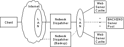
You can use Network Dispatcher with a group of Web Server Caches to create a Scalable High Availability Cache. A Scalable High Availability Cache (SHAC) consists of one or two Network Dispatcher machines (the second would be used to provide a backup for the first), two or more Web Server Cache machines, and at least one back end server. Figure 9 shows an example of an SHAC setup. The Network Dispatcher machine load balances client traffic to the cache machines and the cache machines serve the files from the cache or get the files from the back end servers if the files have not been cached.
In the Network Dispatcher machine, you must configure the cluster and the port, and the mode of the port must be set to extcache to indicate that it is load balancing an external scalable cache array. See the add port command on "Add". Under the port, the cache machines are configured as servers. As with other servers, the interface IP addresses of the caches are used for the unique server IP addresses configured in the Network Dispatcher machine. The advisor and manager are critical to SHAC. The HTTP advisor must be enabled in the Network Dispatcher machine on any ports for which there are external caches (i.e. the port mode is extcache). The advisor queries are used to determine whether the caches are operational. The manager must be enabled and the manager proportions must be set to include advisor input in the weight calculations (i.e. set the advisor percentage to a value greater than 0).
When you configure a cache as a server under a cluster/port on the Network Dispatcher machine, you must also configure the same cluster and port in the Network Dispatcher function on the cache machine. The ports defined in the cache machines must be set to mode cache and the backend servers are defined as servers under these ports. The HTTP advisor should also be run in the cache machines so they will be able to determine backend server load and availability.
Figure 9. Lan Connected Servers
 |